ATmega32 ADC for Light and Temperature Sensors
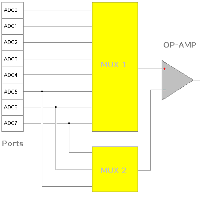
This tutorial shows how to implement the Analogue to Digital Converter (ADC) function on ATMega32 using C code. It consists of code examples, and the meaning of relevant nomenclature such as sampling rate, and resolution. However before we get to the code, let us start from the beginning. The ATMega32 has a built-in 10-bit ADC. The input to this ADC has a multiplexer to provide eight single-ended channels, where each channel can have a dedicated sensor such as an LDR or a Thermistor to provide an input voltage. These channels share the GPIO pins 33 to 40 on Port A. The output from the multiplexer feeds the non-inverting input of an operational amplifier with programmable gain. The gain is available in the following steps, 0 dB (1×), 20 dB (10×), and 46 dB (200×). There is also an option to have three differential inputs by way of ADC5, ADC6, and ADC7, which feeds a second multiplexer connecting to the inverting input side of the op-amp.
From a hardware consideration, the AVCC pin provides voltage to the ADC circuitry and Port A also. This pin requires connection to the Vcc voltage supply, even when the ADC is not used. However when using the ADC, you should also include a filter capacitor as the ADC requires an extremely clean power supply. The ADC also has a dedicated clock circuit, which allows the programmer to shut-off all the other clocks to reduce noise and therefore increase its precision.
ADMUX Register
| 7 | 6 | 5 | 4 | 3 | 2 | 1 | 0 |
| REFS1 | REFS0 | ADLAR | MUX4 | MUX3 | MUX2 | MUX1 | MUX0 |
| REFS1 | REFS0 | Methods for selecting Voltage Reference |
| 0 | 0 | AREF, Internal Vref turned OFF |
| 0 | 1 | AVCC with external capacitor at AREF pin |
| 1 | 0 | Reserved |
| 1 | 1 | Internal 2.56 V Voltage Reference with external capacitor at AREF pin |
The ADC requires a reference voltage to determine the conversion range. The analogue signal for sampling must be between ground and Vref for capture.
For most applications, Vcc is sufficient by setting bit REFS0 to binary 1. Vcc is prone to noise so as a result an external decoupling capacitor helps filter this noise.
ADMUX |= _BV (REFS0);
Analog Channel and Gain Selection Bits
In the ADMUX register, the first four "MUX bits" organise as follows. The first seven numbers select single-ended input configuration. From eight onwards you can select a combination of differential inputs with different gain factors. The gain factor is available only for differential inputs.
| MUX 4,3,2,1,0 |
Single Ended | +Differential Input |
-Differential Input | Gain factor |
| 00000 | ADC0 | NOT AVAILABLE | ||
| 00001 | ADC1 | |||
| 00010 | ADC2 | |||
| 00011 | ADC3 | |||
| 00100 | ADC4 | |||
| 00101 | ADC5 | |||
| 00110 | ADC6 | |||
| 00111 | ADC7 | |||
| 01000 | N/A | ADC0 | ADC0 | 10× |
| 01001 | ADC1 | ADC0 | ||
| 01010 | ADC0 | ADC0 | 200× | |
| 01011 | ADC1 | ADC0 | ||
| 01100 | ADC2 | ADC2 | 10× | |
| 01101 | ADC3 | ADC2 | ||
| 01110 | ADC2 | ADC2 | 200× | |
| 01111 | ADC3 | ADC2 | ||
| 10000 | ADC0 | ADC1 | 1× | |
| 10001 | ADC1 | ADC1 | 1× | |
| 10010 | ADC2 | ADC1 | 1× | |
| 10011 | ADC3 | ADC1 | 1× | |
| 10100 | ADC4 | ADC1 | 1× | |
| 10101 | ADC5 | ADC1 | 1× | |
| 10110 | ADC6 | ADC1 | 1× | |
| 10111 | ADC7 | ADC1 | 1× | |
| 11000 | ADC0 | ADC2 | 1× | |
| 11001 | ADC1 | ADC2 | 1× | |
| 11010 | ADC2 | ADC2 | 1× | |
| 11011 | ADC3 | ADC2 | 1× | |
| 11100 | ADC4 | ADC2 | 1× | |
| 11101 | ADC5 | ADC2 | 1× | |
| 11110 | 1.22 V (VBG) | N/A | ||
| 11111 | 0 V (GND) | |||
In a simple case, we can use a single-ended input. Any port from ADC0 to ADC7 will work. The ADC port can be any number from 0 to 7 and passed through the following functions.
- ReadADC(uint8_t ADCport);
- ADCport=ADCport & 0b00000111;
- ADMUX|=ADCport;
ADCSRA - Control and Status Register
| 7 | 6 | 5 | 4 | 3 | 2 | 1 | 0 |
| ADEN | ADSC | ADATE | ADIF | ADIE | ADPS2 | ADPS1 | ADPS0 |
ADCSRA |= _BV (ADEN);
Bit 7 – ADEN: Set this to binary 1 to enable the microcontroller ADC circuits, whilst binary 0 will switch it OFF.
ADCSRA |= _BV (ADSC);
Bit 6 – ADSC: Setting ADSC bit to binary 1 starts the conversion process. This bit clears automatically when the conversion process completes. Therefore, this bit provides an indication that the conversion has completed.
While (ADCSRA & _BV (ADSC));
This while loop waits for the ADSC bit to become binary 0 again.
ADPS2, ADPS1, ADPS0
These bits determine the division factor between the XTAL frequency and the ADC input clock. Converting an analogue signal to digital requires a clock frequency for the approximation circuitry. This principle is similar to the strips under a curve in maths class. The more strips the better the approximation of the analogue signal. A frequency between 50 kHz and 200 kHz is typical for maximum resolution.
The prescaler frequency is a fraction of the crystal frequency, usually achieved by using a division factor. The bits ADPS2, ADPS1, ADPS0, determine the division factor.
| ADPS2 | ADPS1 | ADPS0 | Division Factor |
| 0 | 0 | 0 | 2 |
| 0 | 0 | 1 | 2 |
| 0 | 1 | 0 | 4 |
| 0 | 1 | 1 | 8 |
| 1 | 0 | 0 | 16 |
| 1 | 0 | 1 | 32 |
| 1 | 1 | 0 | 64 |
| 1 | 1 | 1 | 128 |
16000000 / 128 = 125 kHz
This ATMega32 development board has a 16 MHz crystal; therefore, a division of 128 provides 125 kHz for the prescaler frequency.
ADCSRA |= _BV (ADPS2) | _BV (ADPS1) | _BV (ADPS0);
This value is within the maximum resolution range so we choose a prescaler division factor of 128 by setting bits ADPS2, ADPS1, ADPS0 to binary 1.
ADC Example C Code
This program displays the sampled ADC value on HyperTerminal, so you will need a working UART circuit. Make sure you have a working MAX232 interfacing circuit connected to the UART. Make sure you have tested the UART communications with HyperTerminal using uart.h and uart.c include files as shown in the following section. ATMega32 UART PC Interface - Testing
1: /*******************************************
2: Author: Peter J. Vis
3: Last Updated: 8 Dec 2009
4:
5: Microcontroller: ATmega32
6: Crystal: 16 MHz
7: Platform: Development System
8:
9: URL: https://www.petervis.com
10:
11: LIMITATIONS:
12: No part of this work may be used for
13: commercial use without prior written
14: permission. This program can not be used by
15: bloggers for blogging purposes.
16:
17:
18: PURPOSE:
19: To test LDR Sensor. To calibrate for maximum
20: and minimum values.
21:
22: CIRCUIT:
23: LDR connected to ADC2 port of the ATmega32
24: ********************************************/
25:
26: #define F_CPU 16000000UL
27:
28: #include <avr/io.h>
29: #include <util/delay.h>
30: #include "uart.h"
31: #include "uart.c"
32:
33:
34: // prototypes
35: void initADC();
36: void uart_init();
37: uint16_t ReadADC(uint8_t ADCport);
38:
39: int main()
40: {
41: uint8_t i;
42: uint16_t analog_value;
43:
44: // init ADC
45: initADC();
46:
47: // init UART - this function is
48: // in an external file
49: uart.c
50:
51: // This is needed to make printf
52: // work to send characters to HyperTerminal.
53:
54:
55: uart_init();
56:
57: // init HyperTerminal by sending VT100
58: // escape sequences.
59: printf("\x1B[2J\x1B\x63");
60:
61: // Print a welcome message.
62: printf("Are you ready to calibrate? \r\n");
63:
64:
65: while(1)
66: {
67:
68: //Read LDR Sensor on port ADC02
69: ReadADC(2);
70:
71: // Read the result from the ADC register
72: analog_value = ADC;
73:
74: // Move the HyperTerminal cursor to
75: // the next line.
76: // [2;1H moves the cursor to Row 2,Column 1.
77: // 2K erases the line.
78:
79: printf("\x1B[2;1H\x1B[2K");
80:
81: // Print a 10-bit analog value to
82: // HyperTerminal,
83: printf("ADC value: %u\r\n", analog_value);
84:
85: // Wait 100 ms
86: for(i=0; i<10; i++)
87: _delay_ms(10);
88: }
89:
90: return 0;
91: }
92:
93:
94:
95:
96: // This function will initialize the ADC for
97: // the correct Vref and Prescaler and then
98: // enable it.
99:
100:
101:
102: void initADC()
103: {
104: // Initialise the ADC.
105: // Select Vref -> AVcc with external
106: // capacitor at the AREF pin.
107: ADMUX |= _BV(REFS0);
108:
109: // Select the prescaler of 128
110: ADCSRA |= _BV(ADPS2) | _BV(ADPS1) |
111: _BV(ADPS0);
112: // Enable the ADC.
113: ADCSRA |= _BV(ADEN);
114:
115: }
116:
117:
118: /******************************************
119: This function will read the ADC value from
120: the ADC port specified.
121:
122: Port values: My system has 3 different
123: sensors on respective ports.
124: Therefore, you must pass the port number to
125: the function for the sensor you require.
126:
127: ADCPort Circuit
128: 0 Analog Input
129: 1 Thermistor
130: 2 LDR
131:
132: *******************************************/
133: uint16_t ReadADC(uint8_t ADCport)
134: {
135:
136: ADCport=ADCport&0b00000111;
137: ADMUX|=ADCport;
138:
139: // Start the single conversion mode process.
140: ADCSRA |= _BV(ADSC);
141:
142: // Wait for the conversion to finish.
143:
144: // The ADC signals that it has completed by
145: // automatically clearing the ADSC bit.
146:
147: // Wait in a while loop until the bit
148: // clears.
149: while( ADCSRA & _BV(ADSC) );
150:
151: return(ADC);
152: }